

Study on the Influence of Deformation Mode Assumption on Plastic Deformation of Circular Plates Under Impact Loading
-
摘要: 为了找到一种适用于冲击加载条件下可靠普适的圆板塑性变形模式,首先基于能量法建立了冲击加载下可考虑不同变形模式及材料应变率效应的圆板塑性变形计算模型,然后利用计算模型与试验结果对比分析了不同变形模式假定对圆板最终塑性变形的影响规律. 研究表明:不同的变形模式假定给出了不同的膜拉伸应变空间分布以及膜拉伸平均应变率效应,改变了塑性变形吸能特性,最终影响圆板的塑性变形值;抛物线型变形模式具有误差小、材料适用范围广的优势,建议在后续的评估中采用.Abstract: To find a reliable and universal plastic deformation mode of circular plates under impact loading, based on the energy method, a plastic deformation calculation model for circular plates under impact loading was established, with different deformation modes and material strain rate effects considered. Then the calculation model was compared with the experimental results to analyze the calculation deviation of plastic deformation of circular plates under different deformation modes. The results show that, different deformation mode assumptions give different spatial distributions of membrane tensile strain and different membrane tensile average strain rate effects, which changes the energy absorption characteristics of plastic deformations and finally affects the plastic deformation values of circular plates. The parabolic deformation mode has the advantages of small errors and wide application ranges for materials, and is suitable for the subsequent engineering evaluation.
-

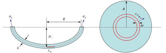
图 1 瞬动加载下圆板最终变形示意图
Figure 1. Schematic diagram of the circular plate deformation under impulsive loading

图 2 瞬动加载下的膜拉伸应变平均值计算示意图
Figure 2. Schematic diagram for calculating the average tensile strain of the membrane under impulsive loading

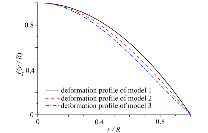
图 3 三种变形模式下圆板变形轮廓空间分布
注 为了解释图中的颜色,读者可以参考本文的电子网页版本,后同.
Figure 3. Spatial distributions of deformation profiles of the circular plate under 3 deformation modes

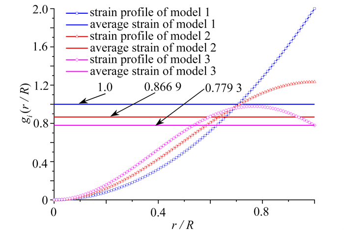
图 4 三种变形模式下圆板膜拉伸应变空间分布及均值
Figure 4. Spatial distributions and mean values of tensile strains of the circular plate membrane under 3 deformation modes

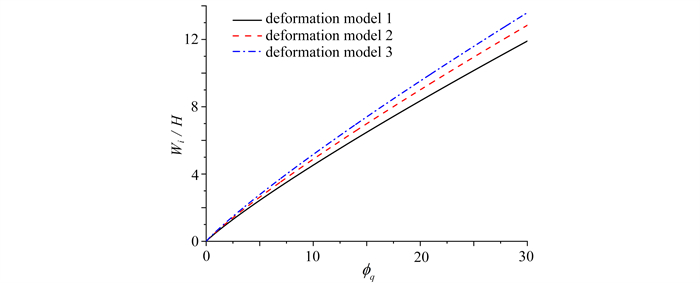
图 5 三种变形模式下圆板无量纲最终塑性变形值随无量纲加载冲量的变化图
Figure 5. Variations of dimensionless final plastic deformation values of the circular plate with dimensionless loading impulse under 3 deformation modes
表 1 Nurick钢板试验工况与模型计算对比结果[12]
Table 1. Comparative results of Nurick steel plate test conditions and model calculations[12]
test H/mm I/(N·s) We/mm We/H W1/mm W1/H error 1/% W2/mm W2/H error 2/% W3/mm W3/H error 3/% 1 1.6 9.0 10.62 6.64 10.43 6.52 -1.85 11.25 7.03 5.87 11.90 7.44 12.01 2 1.6 9.5 10.90 6.81 10.94 6.84 0.38 11.80 7.37 8.26 12.48 7.80 14.55 3 1.6 5.6 6.14 3.84 6.85 4.28 11.49 7.39 4.62 20.21 7.81 4.88 27.16 4 1.6 10.0 11.96 7.48 11.44 7.15 -4.39 12.34 7.71 3.13 13.06 8.16 9.11 5 1.6 9.9 12.08 7.55 11.34 7.09 -6.11 12.23 7.65 1.27 12.94 8.09 7.15 6 1.6 10.8 12.26 7.66 12.24 7.65 -0.10 13.21 8.25 7.76 13.97 8.73 14.02 7 1.6 10.6 12.20 7.63 12.04 7.53 -1.34 12.99 8.12 6.42 13.75 8.59 12.60 8 1.6 10.8 12.80 8.00 12.24 7.65 -4.34 13.21 8.25 3.18 13.97 8.73 9.17 9 1.6 11.5 13.62 8.51 12.94 8.09 -4.97 13.96 8.72 2.50 14.77 9.23 8.46 10 1.6 11.7 13.22 8.26 13.14 8.21 -0.60 14.17 8.86 7.22 14.99 9.37 13.45 11 1.6 11.4 14.00 8.75 12.84 8.02 -8.29 13.85 8.66 -1.07 14.66 9.16 4.68 12 1.6 12.6 14.90 9.31 14.02 8.76 -5.89 15.12 9.45 1.52 16.00 10.00 7.43 13 1.6 12.4 14.60 9.31 13.82 8.64 -7.20 14.91 9.32 0.11 15.78 9.86 5.93 14 1.6 12.9 15.28 9.55 14.31 8.94 -6.34 15.44 9.65 1.03 16.34 10.21 6.91 15 1.6 12.8 16.08 10.05 14.21 8.88 -11.61 15.33 9.58 -4.65 16.22 10.14 0.90 16 1.6 13.6 16.30 10.19 14.99 9.37 -8.07 16.17 10.11 -0.82 17.11 10.69 4.95 17 1.6 13.4 16.38 10.24 14.80 9.25 -9.69 15.96 9.98 -2.58 16.89 10.56 3.09 18 1.6 14.1 17.70 11.06 15.47 9.67 -12.58 16.69 10.43 -5.69 17.66 11.04 -0.20 19 1.6 13.8 17.06 10.66 15.18 9.49 -10.99 16.38 10.24 -3.97 17.33 10.83 1.61 20 1.6 14.7 18.56 11.60 16.04 10.03 -13.55 17.31 10.82 -6.73 18.32 11.45 -1.31 21 1.6 15.6 19.60 12.40 16.90 10.56 -14.82 18.23 11.40 -8.10 19.30 12.06 -2.75  下载: 导出CSV
表 2 Symonds钢板试验工况与模型计算对比结果[13]
Table 2. Comparative results of Symonds steel plate test conditions and model calculations[13]
test H/mm I/(N·s) We/mm We/H W1/mm W1/H error 1/% W2/mm W2/H error 2/% W3/mm W3/H error 3/% 1 1.9 7.09 12.29 6.37 11.03 5.71 -10.29 11.90 6.16 -3.20 12.59 6.52 2.44 2 1.9 3.12 5.00 2.59 5.37 2.78 7.26 5.79 3.00 15.68 6.12 3.17 22.39 3 1.9 5.41 9.88 5.11 8.71 4.51 -11.84 9.40 4.87 -4.89 9.94 5.15 0.65 4 1.9 5.54 9.75 5.05 8.90 4.61 -8.79 9.60 4.97 -1.59 10.16 5.26 4.14 5 1.9 3.15 5.28 2.74 5.41 2.80 2.47 5.84 3.02 10.52 6.18 3.20 16.93 6 1.9 4.55 7.98 4.13 7.48 3.87 -6.22 8.07 4.18 1.16 8.54 4.42 7.05 7 1.9 6.95 12.34 6.39 10.84 5.62 -12.16 11.70 6.06 -5.22 12.38 6.41 0.30
下载: 导出CSV
表 3 Symonds钛板试验工况与模型计算对比结果[13]
Table 3. Comparative results of Symonds titanium plate test conditions and model calculations[13]
test H/mm I/(N·s) We/mm We/H W1/mm W1/H error 1/% W2/mm W2/H error 2/% W3/mm W3/H error 3/% 1 2.3 5.26 8.41 3.60 9.56 4.09 13.65 10.29 4.40 22.34 10.87 4.65 29.25 2 2.3 7.06 11.33 4.84 12.59 5.39 11.11 13.55 5.80 19.61 14.32 6.13 26.37 3 2.3 5.57 9.22 3.95 10.09 4.32 9.41 10.86 4.65 17.77 11.47 4.91 24.42 4 2.3 5.43 8.92 3.82 9.85 4.21 10.46 10.60 4.54 18.90 11.20 4.79 25.61 5 2.3 3.54 5.77 2.47 6.60 2.82 14.42 7.10 3.04 23.15 7.50 3.21 30.10 6 2.3 6.58 11.13 4.76 11.79 5.05 5.98 12.69 5.43 14.08 13.41 5.74 20.53 7 2.3 5.94 10.24 4.38 10.71 4.58 4.60 11.53 4.93 12.60 12.18 5.21 18.95 8 2.3 6.34 10.85 4.64 11.38 4.87 4.95 12.25 5.24 12.98 12.95 5.54 19.36 9 2.3 4.71 8.00 3.42 8.62 3.69 7.74 9.28 3.97 15.98 9.80 4.20 22.52 10 2.3 3.60 5.97 2.55 6.69 2.86 12.08 7.20 3.08 20.63 7.61 3.26 27.43 11 2.3 7.06 12.67 5.43 12.58 5.38 -0.75 13.54 5.80 6.84 14.31 6.12 12.88
下载: 导出CSV
表 4 三种变形模式假定下模型与试验平均误差
Table 4. Average errors of the model and the test under the assumption of 3 deformation modes
test case deformation mode 1 deformation mode 2 deformation mode 3 Nurick’steel plate 6.89% 4.86% 7.97% Symonds’steel plate 8.43% 6.04% 7.70% Symonds’titanium plate 8.65% 16.81% 23.40%
下载: 导出CSV
-
[1] JONES N. Structural Impact[M]. UK: Cambridge University Press, 1989. [2] JONES N. Recent studies on the dynamic plastic behavior of structures[J]. Applied Mechanics Reviews, 1989, 42(4): 95-115. doi: 10.1115/1.3152425 [3] NURICK G N, MARTIN J B. Deformation of thin plates subjected to impulsive loading: a review part Ⅱ: experimental studies[J]. International Journal of Impact Engineering, 1989, 8(2): 171-186. doi: 10.1016/0734-743X(89)90015-8 [4] NURICK G N, MARTIN J B. Deformation of thin plates subjected to impulsive loading: a review part Ⅰ: theoretical considerations[J]. International Journal of Impact Engineering, 1989, 8(2): 159-170. doi: 10.1016/0734-743X(89)90014-6 [5] 余同希, 陈发良. 用"膜力因子法" 分析简支刚塑性圆板的大挠度动力响应[J]. 力学学报, 1990, 22(5): 555-565.YU Tongxi, CHEN Faliang. Analysis of the large deflection dynamic response of simply-supported circular plates by the "membrane factor method"[J]. Acta Mechanica Sinica, 1990, 22(5): 555-565. (in Chinese) [6] YUEN S C K, NURICK G N, LANGDON G S, et al. Deformation of thin plates subjected to impulsive load: part Ⅲ: an update 25 years on[J]. International Journal of Impact Engineering, 2017, 107: 108-117. doi: 10.1016/j.ijimpeng.2016.06.010 [7] CLOETE T J, NURICK G N. On the influence of radial displacements and bending strains on the large deflections of impulsively loaded circular plates[J]. International Journal of Mechanical Sciences, 2014, 82: 140-148. doi: 10.1016/j.ijmecsci.2014.02.026 [8] DUFFEY T A. The large deflection dynamic response of clamped circular plates subjected to explosive loading: Research Report SC-RR-67-532[R]. Sandia National Laboratories, 1967. [9] WEN H M, YU T X, REDDY T Y. A note on clamped circular plates under impulsive loading[J]. Mechanics of Structures and Machines, 1995, 23(3): 331-342. doi: 10.1080/08905459508905241 [10] TEELING-SMITH R G, NURICK G N. The deformation and tearing of thin circular plates subjected to impulsive loads[J]. International Journal of Impact Engineering, 1991, 11(1): 77-91. doi: 10.1016/0734-743X(91)90032-B [11] GHARABABAEI H, DARVIZEH A. Experimental and analytical investigation of large deformation of thin circular plates subjected to localized and uniform impulsive loading[J]. Mechanics Based Design of Structures and Machines, 2010, 38(2): 171-189. doi: 10.1080/15397730903554633 [12] NURICK G N. Large deformations of thin plates subjected to impulsive loading[D]. South Africa: University of Cape Town, 1987. [13] BODNER S R, SYMONDS P S. Experiments on viscoplastic response of circular plates to impulsive loading[J]. Journal of the Mechanics and Physics of Solids, 1979, 27(2): 91-113. doi: 10.1016/0022-5096(79)90013-9 -

计量
- 文章访问数: 49
- HTML全文浏览量: 17
- PDF下载量: 5
- 被引次数: 0

 渝公网安备50010802005915号